
I’ve been building my home-lab since 2020, relying on a Mikrotik Chateau as my main router and firewall. It served me well, but as the lab grew, the 1 gigabit ceiling started causing real bottlenecks. With a 1 gigabit internet connection, even a single large download can saturate the network — and I’m also running an NFS share, streaming high bit-rate 4K movies through Jellyfin, and hosting a whole pile of other services.
Since starting my NixOS journey back in early 2024, I figured it would be a great project to build my next router and firewall with NixOS at the core, but on hardware with 2.5 gigabit capabilities. This post walks through the full setup: PPPoE, VLAN segmentation, link aggregation, nftables firewall rules, Kea DHCP, and Blocky DNS with ad blocking.
The Hardware
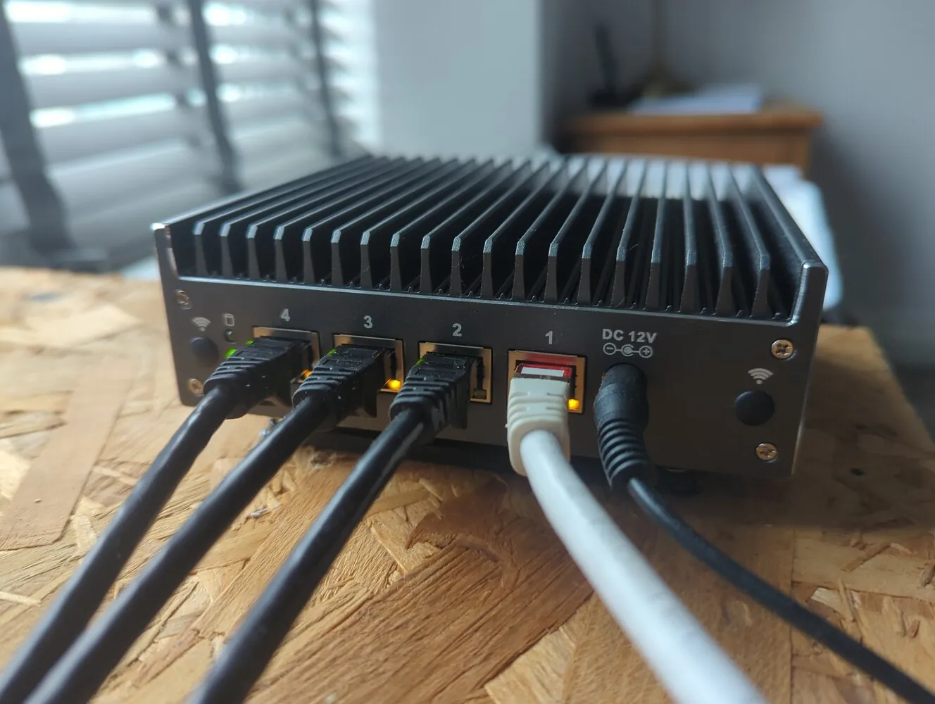
For this project I opted for the Protectli Vault Pro VP2420-4:
| Type | Spec |
|---|---|
| CPU | Intel Celeron J6412 (2.0 GHz Base, 2.6 Burst, 1.5M Cache) |
| Cores/Threads | 4/4 |
| Network | 4x Intel I226-V 2.5G Ethernet, RJ-45 |
| Video | Intel UHD Graphics for 10th Gen, 1x HDMI 1.4, 1x DP 1.4 |
| RAM | 1x SO-DIMM DDR4-3200, Max 32GB |
| Storage | 1x SATA SSD, 1x M.2 SATA, 1x 16G eMMC on board |
This is probably a little overkill for a home-lab router, but as I like to self-host absolutely everything, it has the ability to do much more than just routing and firewalling. For example, I can declare a NixOS container as a webserver and forward HTTP/HTTPS traffic to it for hosting my websites. So it should prove to be a very capable addition that will let me manage and expand my ever-growing network — and host several other critical services too — without facing bandwidth bottlenecks.
Of course, in time I imagine the 2.5 gigabit limit will start to become a problem. But the beauty of NixOS is that the router configuration I’ve built for this device is highly portable. If I ever decide to upgrade to 10 gigabit networking (probably when fan-less 10G mini-PCs hit the market), migrating this configuration to a new device will be a walk in the park.
NixOS Configuration
I already have an extensive multi-host NixOS configuration hosted here. The final configuration for this router setup is on this host. Since writing this blog, I’ve been working on this configuration for a couple of years (with almost 1500 commits to date!), and already have much of my network configured using it. I also have a separate private repository with secrets (using sops-nix), IP addresses, and other information I don’t wish to share publicly, which feeds into my NixOS configuration as a flake input. These repositories serve as a central point for delivering configuration variables to all my systems. This actually makes reconfiguring my whole network — half a dozen devices and many containers — very easy. I just need to modify a single variable in my configuration, and it will eventually permeate to all of my systems automatically.
Storage and RAM
As I ordered the bare-bones version of the Protectli VP2420-4, the device needs storage and RAM. I had an old 16GB RAM stick lying around from when I upgraded my laptop to 32GB, and I also had an old 256GB SSD from my old gaming PC.
Note: Originally, I did purchase an M.2 NVMe drive for this build, but I missed the part where the Protectli Vault only supports M.2 SATA SSD drives. I didn’t realise there was a difference, so just be aware of this if purchasing this device!
I declaratively formatted the disk with BTRFS using Disko.
I gave 1GB for the boot partition. With NixOS, I’d say this is a minimum, as your boot partition can quickly fill up with different kernel versions in order to support previous configurations (I’ve set garbage collection to every 30 days). I’ve had issues in the past with my boot partition filling up, which is a bit of a pain to fix. So 1-2GB seems to add enough headroom for this — when I used Arch Linux, I used to allocate just 256MB.
IP Forwarding
The first step in setting up a Linux device as a router is to enable the kernel to forward IP packets between network interfaces.
boot.kernel.sysctl = {
  "net.ipv4.ip_forward" = true;
  "net.ipv4.conf.all.forwarding" = true;
  "net.ipv6.conf.all.forwarding" = true;
  "net.ipv4.conf.all.arp_filter" = 1;
  "net.ipv4.conf.default.arp_filter" = 1;
};
This enables IPv4 and IPv6 forwarding, plus ARP filtering for enhanced security.
Configure PPPoE
My ISP provides my WAN internet connection via PPPoE, so I need to set up a session using ppp. There’s a NixOS module for this that allows for easy configuration:
# setup pppoe session
services.pppd = {
  enable = true;
  peers = {
    # pppoe-wan is the name of the service
    pppoe-wan = {
      autostart = true;
      enable = true;
      config = ''
        plugin pppoe.so br-wan
        name "bthomehub@btbroadband.com"

        noipdefault
        hide-password
        lcp-echo-interval 1
        lcp-echo-failure 4
        noauth
        persist
        maxfail 0
        holdoff 5
        mtu 1500
        noaccomp
        default-asyncmap
        +ipv6
        ipv6cp-use-ipaddr
      '';
    };
  };
};
This sets up a PPPoE connection on the WAN VLAN interface. I’ve set the WAN VLAN to be tagged with VID 99 (more details on this later). The WAN connection comes into my property via FTTP (Fiber to the Premises) and is connected to the ISP-provided ONT box. I then connect this to my network via Ethernet cable, which plugs into a managed switch where I tag the WAN traffic with VID 99. This is then transmitted via a trunk cable to my new router.
Here’s what the ppp daemon configuration settings do:
plugin pppoe.so br-wan: Loads PPPoE plugin for WAN bridge interface (calledbr-wan).name "bthomehub@btbroadband.com": Sets the ISP username for authentication.noipdefault: Prevents assuming a local IP; waits for ISP to assign.hide-password: Hides password in logs for security.lcp-echo-interval 4: Sets 4-second interval for LCP echo requests (checks if link is still alive).lcp-echo-failure 4: Declares link down after 4 unanswered echo requests.noauth: Disables asking peer for authentication.persist: Keeps trying to reconnect indefinitely after drops.maxfail 0: Unlimited retry attempts for connection.holdoff 5: Waits 5 seconds before reconnect attempts.mtu 1500: Sets the MTU to 1500 bytes.+ipv6: Enables IPv6 support on the link.ipv6cp-use-ipaddr: Uses IPv4 address for IPv6 link-local configuration.
PPPoE Pre- and Post-Start Scripts
There’s some pre- and post-configuration that needs to happen around the PPPoE connection.
The systemd.services."pppd-pppoe-wan".preStart option manually sets the MTU of my interface to 1512. This is called Baby Jumbo Frames, and is required for PPPoE over a VLAN trunk connection. This allows the default 1500 MTU for the Ethernet frame, plus 8 and 4 bytes to account for the PPPoE and VLAN headers. Without this, fragmentation would occur when transmitting packets through the network.
After that, I’ve created a ppp post-hook script in /etc/ppp/ip-up. This ensures that when the PPPoE connection (ppp0) comes up, the system logs the event and sets up default network routes through that interface — essential for routing all outbound traffic through the PPPoE connection. The /etc/ppp/ip-down script does the opposite when the connection drops.
systemd.services."pppd-pppoe-wan".preStart = ''
  ${pkgs.iproute2}/bin/ip link set enp1s0 mtu 1512
'';

environment.etc.ppp-up = {
  # this script runs after PPP has established a connection
  # we'll use it to log, and add the default IPv4 and IPv6 routes
  enable = true;
  target = "ppp/ip-up";
  mode = "0755";
  text = ''
    #!${pkgs.bash}/bin/bash
    ${pkgs.logger}/bin/logger "$1 is up"
    if [ $IFNAME = "ppp0" ]; then
      ${pkgs.logger}/bin/logger "PPPoE online"

      ${pkgs.logger}/bin/logger "Add default routes via PPPoE"
      ${pkgs.iproute2}/bin/ip route add default dev ppp0 scope link metric 100
      ${pkgs.iproute2}/bin/ip -6 route add default dev ppp0 scope link metric 100
    fi
  '';
};

environment.etc.ppp-down = {
  # this script runs after the PPP connection drops
  # we'll use it to log, and remove the default routes
  enable = true;
  target = "ppp/ip-down";
  mode = "0755";
  text = ''
    #!${pkgs.bash}/bin/bash
    ${pkgs.logger}/bin/logger "$1 is down"
    if [ $IFNAME = "ppp0" ]; then
      ${pkgs.logger}/bin/logger "PPPoE offline"

      ${pkgs.logger}/bin/logger "Remove default routes via PPPoE"
      ${pkgs.iproute2}/bin/ip route del default dev ppp0 scope link metric 100
      ${pkgs.iproute2}/bin/ip -6 route del default dev ppp0 scope link metric 100

    fi
  '';
};
Link Aggregation
The Protectli Vault has 4x 2.5GB RJ-45 ports. One port is for the WAN connection, and the other three are bonded into a single link aggregation interface (called bond0) that connects to my main network switch. This gives a total theoretical bandwidth of 7.5 gigabits per second in and out of the router at any given time. Any single connection is still limited to 2.5GB (the bandwidth of an individual port), but this allows several connections to exist concurrently totalling up to 7.5GB. This is useful for my network where there is a lot of traffic from multiple sources.
Setting up a link-aggregated port in NixOS is straightforward:
bonds.bond0 = {
  interfaces = ["enp2s0" "enp3s0" "enp4s0"];
  driverOptions = {
    miimon = "100";
    mode = "balance-rr";
    xmit_hash_policy = "layer3+4";
  };
};
This creates an interface called bond0, connected to three of the physical ports on my device. I’m using the balance-rr mode, which stands for balance round-robin. This distributes packets evenly across all three ports.
I’ve done some concurrent iPerf3 testing on this connection, and can get between 5-7 GB combined total transfer speeds. I think the bottleneck in my system is the 2.5GB managed switch that I’m using (which I intend to upgrade at some point).
Bridge, VLAN, and Interface Configuration
Bridges
I’ve created a base bridge interface called br0, which connects the physical interfaces on the device. bond0 is a combination of enp2s0, enp3s0, and enp4s0. enp1s0 is the WAN connection.
I then create separate bridges for each of the VLAN interfaces (which are configured in the next section).
bridges = {
  br0.interfaces = ["bond0" "enp1s0"];
  br-wan.interfaces = ["wan"];
  br-access.interfaces = ["access"];
  br-admin.interfaces = ["admin"];
  br-home.interfaces = ["home"];
  br-guest.interfaces = ["guest"];
  br-external.interfaces = ["external"];
  br-iot.interfaces = ["iot"];
};
VLANs
So far, my network has 7 VLANs:
| VLAN Name | ID | Purpose | Subnet | Bridge |
|---|---|---|---|---|
| wan | 99 | Internet uplink | public IP | br-wan |
| access | 1 | Infra devices | 192.168.1.0/24 | br-access |
| admin | 10 | Admin devices | 192.168.10.0/24 | br-admin |
| home | 20 | Home devices | 192.168.20.0/24 | br-home |
| guest | 30 | Guests (untrusted devices) | 192.168.30.0/24 | br-guest |
| external | 40 | DMZ | 192.168.40.0/24 | br-external |
| iot | 50 | IoT devices | 192.168.50.0/24 | br-iot |
VLANs are defined and attached to the base br0 interface:
vlans = {
  wan = {
    id = 99;
    interface = "br0";
  };
  access = {
    id = 1;
    interface = "br0";
  };
  admin = {
    id = 10;
    interface = "br0";
  };
  home = {
    id = 20;
    interface = "br0";
  };
  guest = {
    id = 30;
    interface = "br0";
  };
  external = {
    id = 40;
    interface = "br0";
  };
  iot = {
    id = 50;
    interface = "br0";
  };
};
Interface Configuration
Each VLAN bridge is assigned a static IPv4 address as the VLAN gateway (i.e. xx.xx.xx.1). All physical and VLAN interfaces have DHCP disabled since we’re managing addresses ourselves.
interfaces = {
  enp1s0.useDHCP = false;
  enp2s0.useDHCP = false;
  enp3s0.useDHCP = false;
  enp4s0.useDHCP = false;
  br0.useDHCP = false;

  # VLANS
  wan.useDHCP = false;
  access.useDHCP = false;
  admin.useDHCP = false;
  home.useDHCP = false;
  guest.useDHCP = false;
  external.useDHCP = false;
  iot.useDHCP = false;

  # define bridge interface settings
  br-access = {
    useDHCP = false;
    ipv4.addresses = [
      {
        address = "${homelabAddresses.access.gateway}";
        prefixLength = 24;
      }
    ];
  };

  br-admin = {
    useDHCP = false;
    ipv4.addresses = [
      {
        address = "${homelabAddresses.admin.gateway}";
        prefixLength = 24;
      }
    ];
  };

  br-home = {
    useDHCP = false;
    ipv4.addresses = [
      {
        address = "${homelabAddresses.home.gateway}";
        prefixLength = 24;
      }
    ];
  };

  br-guest = {
    useDHCP = false;
    ipv4.addresses = [
      {
        address = "${homelabAddresses.guest.gateway}";
        prefixLength = 24;
      }
    ];
  };

  br-external = {
    useDHCP = false;
    ipv4.addresses = [
      {
        address = "${homelabAddresses.external.gateway}";
        prefixLength = 24;
      }
    ];
  };

  br-iot = {
    useDHCP = false;
    ipv4.addresses = [
      {
        address = "${homelabAddresses.iot.gateway}";
        prefixLength = 24;
      }
    ];
  };
};
Firewall Configuration Using nftables
Below are the nftables firewall rules for my network. I have port forwarding to pass incoming HTTP/HTTPS traffic to my webserver container (in the prerouting chain of the nat table), and forwarding rules to allow certain interfaces to access other parts of the network. For example, I want my media center (called sparky, also configured with NixOS) to be able to access my remotebuilder container.
networking = {
  firewall.enable = false;
  nftables = {
    enable = true;
    ruleset = ''
        table inet filter {
          chain input {
            type filter hook input priority 0; policy drop;

            iifname "lo" counter accept comment "Allow router to talk to itself"

            iifname {
              "br-admin", "br-home", "br-iot"
            } udp dport 5353 counter accept comment "Allow admin, home and IOT VLAN network to access the router"

            iifname {
              "br-admin"
            } counter accept comment "Allow admin VLAN network to access the router"

            # Allow DNS over UDP
            iifname { "br-access", "br-home", "br-guest" } udp dport 53 counter accept comment "Allow DNS over UDP for VLAN networks to access the router"

            # Allow CUPS over TCP for home
            iifname "br-home" tcp dport 631 counter accept comment "Allow CUPS over TCP for VLAN networks to access the router"

            iifname {
              "${wanInterface}"
            } ct state established,related counter accept comment "Allow established traffic"

            iifname {
              "${wanInterface}"
            } counter drop comment "Drop all other traffic from wan"

          }

          chain forward {
            type filter hook forward priority 0; policy drop;

            iifname {
              "br-admin", "br-access", "br-home", "br-guest", "br-external"
            } oifname {
              "${wanInterface}"
            } counter accept comment "Allow trusted LAN to WAN"

            iifname {
              "${wanInterface}"
            } oifname {
              "br-admin", "br-access", "br-home", "br-guest", "br-external"
            } ct state established,related counter accept comment "Allow established back to LANs"

            iifname {
              "br-admin"
            } oifname {
              "br-access", "br-admin", "br-home", "br-guest", "br-external", "br-iot"
            } counter accept comment "Allow admin to access rest of network"

            iifname {
              "br-home"
            } oifname {
              "br-iot"
            } counter accept comment "Allow home to access iot"

            iifname {
              "br-admin", "br-home"
            } oifname {
              "br-iot"
            } udp dport 5353 counter accept comment "Allow admin and home to access iot devices on UDP port 5353 for mDNS"

            iifname "br-home" oifname "br-admin" ip daddr ${remoteBuilderIP} tcp dport 22 counter accept comment "Allow home access to remote builder service"

            iifname {"br-home", "br-access"} oifname "br-admin" ip daddr ${resticBackupIP} tcp dport ${toString resticBackupPort} counter accept comment "Allow home access to restic backup service"

            iifname "br-external" oifname "br-admin" ip daddr ${metricsServerIP} tcp dport ${toString victoriaLogsPort} counter accept comment "Allow external access to remote logger service"

            ct state established,related counter accept

            iifname {
              "${wanInterface}"
            } oifname {
              "br-external"
            } ct state new ct status dnat ip daddr ${webserverIP} tcp dport {80, 443} counter accept comment "Allow new webserver packets to be forwarded to external VLAN interface"

            counter drop comment "Drop all other traffic"

          }

          chain output {
            type filter hook output priority filter; policy accept;
          }
        }

        table ip nat {
          chain prerouting {
            type nat hook prerouting priority filter;
            iifname "${wanInterface}" tcp dport {443, 80} counter dnat to ${webserverIP}
          }
          chain postrouting {
            type nat hook postrouting priority filter;
            oifname "${wanInterface}" masquerade
          }
        }
    '';
  };
};
The full topology of my home-lab network is shown in this graphic (created with Draw.io):

DHCP Server
I’m using the Kea module to configure DHCP on my network. Any device that connects on any of the VLANs will be automatically assigned an IP address by Kea.
I’ve set lease-database to memfile, which tells Kea to keep track of leases in-memory and store a copy on disk in a CSV file. For larger networks, a proper database backend (e.g. PostgreSQL) should probably be used instead.
The interfaces that Kea should listen on are defined in the interfaces-config section. Here I’ve passed the bridge interfaces for each of the VLAN networks.
# Kea DHCP server
services.kea.dhcp4.enable = true;
services.kea.dhcp4.settings = {
  "interfaces-config" = {
    interfaces = ["br-access" "br-admin" "br-home" "br-guest" "br-external" "br-iot"];
    service-sockets-max-retries = 5;
    service-sockets-retry-wait-time = 5000;
  };

  "lease-database" = {
    name = "/var/lib/kea/dhcp4-leases.csv";
    type = "memfile";
    persist = true;
    lfc-interval = 3600;
  };

  valid-lifetime = 4000;
  renew-timer = 1000;
  rebind-timer = 2000;

  "subnet4" = [
    {
      id = 1;
      interface = "br-access";
      subnet = "${homelabAddresses.access.subnet}"; # i.e. 192.168.1.0/24
      pools = [
        {pool = "${homelabAddresses.access.dhcp-pool}";} # The pool of addresses Kea should issue, i.e. 192.168.1.100 - 192.168.1.255
      ];
      option-data = [
        {
          name = "routers";
          data = "${homelabAddresses.access.gateway}"; # Gateway IP for VLAN network, i.e. 192.168.1.1
        }
        {
          name = "domain-name-servers";
          data = "${homelabAddresses.access.gateway}"; # Define DNS server (see Blocky below)
        }
      ];
    }
    {
      id = 10;
      interface = "br-admin";
      subnet = "${homelabAddresses.admin.subnet}"; # i.e. 192.168.10.0/24
      pools = [
        {pool = "${homelabAddresses.admin.dhcp-pool}";}
      ];
      option-data = [
        {
          name = "routers";
          data = "${homelabAddresses.admin.gateway}";
        }
        {
          name = "domain-name-servers";
          data = "${homelabAddresses.admin.gateway}";
        }
      ];
    }
    # ... other interfaces here ...
  ];
};
DNS Server With Ad Blocking Using Blocky
Blocky is a lightweight DNS proxy written in Go that can block certain domains on a local network. It’s similar to Pi-hole, but without a web UI and has a fully configurable module in nixpkgs.
Blocklists can be passed as URLs, defined in blocking.denylists. Here I’m using a combination of a few lists to block malware, ads, and adult content on my home network.
Kea advertises this DNS server to devices that connect via DHCP. Devices with static IPs have their nameserver set to the VLAN gateway — which is the IP that Blocky listens on.
services.blocky = {
  enable = true;
  settings = {
    customDNS = {
      mapping = {
        "home.lan" = "${reverseProxyIP}";
      };
    };
    ports.dns = 53;
    upstreams.groups.default = [
      "https://one.one.one.one/dns-query"
    ];
    log.level = "info";
    bootstrapDns = {
      upstream = "https://one.one.one.one/dns-query";
      ips = ["1.1.1.1"];
    };
    blocking = {
      denylists = {
        ads = [
          "https://raw.githubusercontent.com/StevenBlack/hosts/master/hosts"
          "https://raw.githubusercontent.com/hagezi/dns-blocklists/main/hosts/pro.txt"
          "https://raw.githubusercontent.com/hagezi/dns-blocklists/main/hosts/tif.txt"
          "https://raw.githubusercontent.com/hagezi/dns-blocklists/main/wildcard/dyndns.txt"
          "https://raw.githubusercontent.com/hagezi/dns-blocklists/main/wildcard/hoster.txt"
        ];
        adult = [
          "https://blocklistproject.github.io/Lists/porn.txt"
        ];
      };
      whiteLists = {
        ads = [
          "https://raw.githubusercontent.com/hagezi/dns-blocklists/main/wildcard/whitelist-referral-onlydomains.txt"
        ];
      };
      clientGroupsBlock = {
        default = ["ads" "adult"];
      };
    };
  };
};
Six Months Later
I’ve actually been running this as my main firewall/router at home for about 6 months now. It’s extremely stable, and I’ve not really had any issues with it. I have an automatic update script for my NixOS devices that runs each week — it pulls changes from my remote NixOS repository, updates the flake inputs, then does a full nixos-rebuild boot followed by a restart. So all software packages on my devices are kept up to date according to the latest nixpkgs stable release.
I also have extensive monitoring of all my systems throughout my home-lab (a topic for another blog: “Declarative NixOS Systems Observability using Prometheus and Grafana”), so if any service on my new router fails, it will send an alert straight to my phone.
The networking performance improvement has been massive. My NFS file share is much faster and more responsive. We can now stream games, watch 4K movies, access files, run system backups, and download from the internet all at the same time without any of it grinding to a halt.